The Project:
Construct a full scale, static display reproduction of an SE5a aircraft as operated by 2 Squadron and 6 Training Squadron, Australian Flying Corps (AFC) during the Great War. The AFC operated 161 individual airframes.

2 AFC:
2 AFC converted to the SE5a during December, 1917 which they operated for the remainder of the war. The squadron accounted for at least 181 enemy aircraft either destroyed, out of control or driven down. Casualties amounted to 25 pilots killed and 8 wounded.
6 AFC:
Formed in June, 1917 and lastly based at Minchinhampton, UK, the squadron operated a variety of aircraft.At the time of disbandment in March, 1919, the squadron was operating Avro 504 two seater trainers and SE5a fighters.

Realism:
The SE5a will be as accurate as possible externally. Internal items that do not contribute to the realism will not be included in the design.
CNC:
The project relies heavily on laser cutting for the steel, aluminium and ply components to:
- provide accuracy of complicated shapes
- provide dimensional consistency of duplicated parts
- speed up the build process
3D printing:
The workshop has a 3D printer to produce complicated parts that would be virtually impossible to fabricate given the workshop resources and the volunteer skills available.
3D printing to be done include exhaust, radiator, engine, fuel tank, cockpit, armament and undercarriage parts, and external covers and fairings.
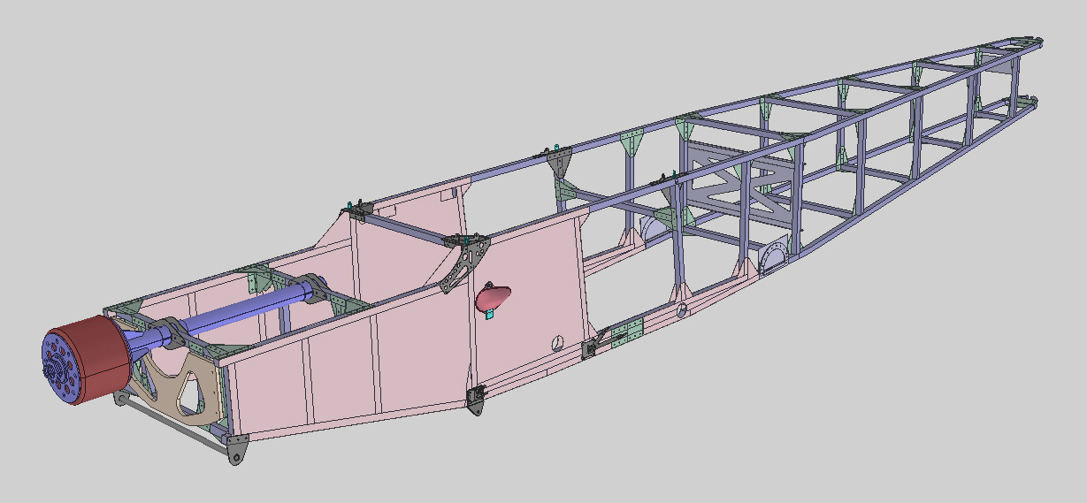
Fuselage:The fuselage is fabricated from 25 x 25 aluminium tube with aluminium skins forward and aluminium / steel gussets.

Top Centre Section:
The centre section has aluminium spars, 12mm ply ribs, 1mm steel parts for the leading edge structure with aluminium skin.

Cabane Struts:
The struts are steel tubes faired with aluminium.

Bottom Centre Section:
The bottom centre section consists of two "stout' steel tube cross members with a ply structure around the tubes.


Coaming:
The coaming consists of the:
- Fuel tank
- Cockpit surround
- Rear turtle deck and faired headrest

The fuel tank has a steel frame and aluminium skin mounted on ply cross members.

Ply skin mounted on ply frames with leather surround around the edge of the cockpit opening.

Rear Turtle Deck:
Pine strips mounted on ply bulkheads over which fabric will be laid.

Armament:
Armament components includes:
- Lewis gun (replica: not shown)
- Foster mount over the top centre section for loading the Lewis gun in flight.
- Vickers gun (replica) in the coaming
- Aldis sight: tube in front of the windscreen
- Ring and bead sight

The firewall components includes the:
- Propeller
- Engine, engine mount and exhaust
- Radiator

The propeller is two bladed made from timber. It is designed to be rotated (by hand).
The museum has bought an original SE5a propeller from World War I for the project. Considering its age, it is in very good condition.
Engine, engine mount and exhaust:
The engine is made of ply stacked on dowel. It is mounted on an engine mount structure of the construction as the fuselage.
The exhaust is fabricated of steel tube and all the red parts are 3D printed.

Radiator:
The radiator is made of a multitude of steel parts and 3D printed parts. The shutters are fixed (do not rotate).
The curved green light green parts and the radiator cap are 3D printed.

Fuselage Underside:
Aluminium cowls on the underside of the fuselage with openings for cooling air to exit.

Wings:
The wings are of the same construction top and bottom.

Wing Panel:
Aluminium spars, ply ribs with cable internal bracing and an aileron on all four panels.

Empennage:Aluminium spars, ply ribs with cable internal bracing and an aileron on all four panels.

Wing Struts:
Solid timber struts, steel end fittings and cable bracing.

Solid timber struts, steel end fittings and cable bracing.

The empennage is a little bit more 'hand made' than the rest of the project.

Fins:
The upper and lower fins are attached to the stern post which is riveted to the fuselage longerons.

Rudder with the observable part of the rudder cables. The cables are doubled up as per the original.

Horizontal Stabiliser:
The horizontal stabiliser is fabricated in two halves and bolted in place, and has hand shaped timber spars.

Elevator:
The elevators are of all timber construction also with hand shaped spars.

External Bracing:
On the actual aircraft, the bracing was streamlined steel but, due to cost considerations, 6mm steel rod with turned end fittings will be used.

Elevator Actuation:
The elevators are actuated via internal cables and pulleys presumably to reduce drag. Triangular inspection windows are placed, in the top and bottom surfaces, at each pulley.

Main Wheels:
The main undercarriage is quite a complicated assembly with timber vee struts rather than the more usual faired steel tube.

Axle:
Main cross member with stub axles (green) for the wheels.

Fairing:
There are two additional cross members to support the ply fairing of the main cross member.

Vee Struts:
Timber vee struts with rather complicated (laser cut) steel plates. Bungee cord is wrapped around the vee strut (at the bottom of the vee) and the main cross member to provide shock absorption.
Tail Skid:
The tail skid rotates with the rudder but is a separate assembly to the rudder. It swivels on the stern post.

Tail Skid Structure:
Under the fairing is a tubular structure.


