2 May 2019

Handley Page 0/400: FULL SCALE

Currently, the AAFM volunteers are building a quarter scale 0/400 which will be suspended from the ceiling in the museum display.


Full Scale:

Over the 18/19 Christmas break, I decided to design a FULL SCALE 0/400 that could be built if anyone was inclined to do so.

To build it would be epic AND it would be the only one in the world. I would build it myself if I had access to a workshop big enough.

As with all my designs, only those features that contribute to the external realism are included.

References:

The main references I used were Windsock Datafiles #116 and 121.

Dimensions:

This is a very large aeroplane. In the first image I have included a 6 foot / 183 cm 'stick guy' to provide scale.
  • Span:   100 ft / 30.5 m (top wing)
  • Length: 62ft 10.5in / 1916 cm
  • Height: 22 ft / 670 cm (in flying position)

Front 3/4:


Rear 3/4:


Fuselage:

The fuselage construction is 40 x 40 aluminium tube with aluminium and steel gussets, and internal cable bracing.


Fuselage Assembly Sequence:

The middle fuselage module is first, then the front and rear fuselage modules, cockpit coaming, front turret and tail cone.


Fuselage Trolley:

Once the fuselage is complete, it is placed on a trolley.


Centre Section:


Centre Section Assembly Sequence:

Mount the 'A' frame struts onto the fuselage then mount the top centre section and stabilise with the flying wires. Install the bottom centre and stabilise with landing wires.


Engine Nacelles and Props:


Radiator:


Nacelle with Skins:


Nacelle Structure:


Nacelle Struts:


Prop and Prop Shaft Mount:


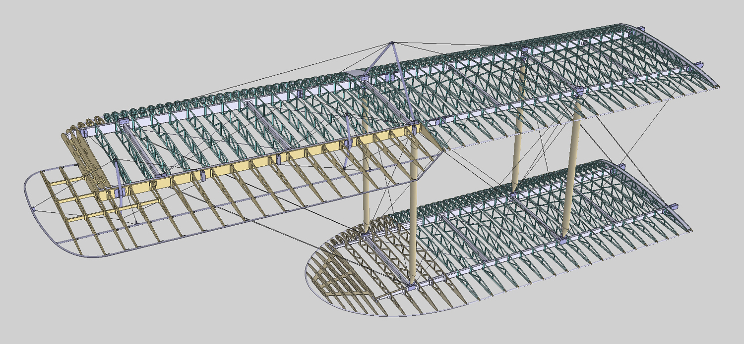
Wing - General Arrangement:


Wing Top:


Wing Bottom:


Aileron:


Struts and External Bracing:


Wing Stand:

The installation of the top wing panel is the trickiest part of the project assembly. Each post of the wing stand has a wind up cable to raise the wing. Additional stands will be required for people to stand on while connecting the wing and attaching the struts and external bracing.

Note: The undercarriage is installed after the wings.


Empennage:


Empennage - General Arrangement:


Fixed Fin and Inboard Struts:


Horizontal Stabilisers:


Rudder:


Rudder Control:


Elevators:


Elevator Control:


External Bracing:


Undercarriage - Main:

The undercarriage is the last major assembly to be installed on to the aircraft. A support is placed under the rear fuselage then the fuselage is raised at the front and the main undercarriage is installed. Finally the tail skid assembly is installed.


Undercarriage - Tail Skid:


15 Apr 2019

1954 MV Agusta Pullman

For many years I have been addicted to 3D computer graphics. The programs I use are:
  • Rhino: for most of the 3D I create
  • T-Splines: for free form (compound) surfaces

Subjects are mainly aviation related but occasionally I fly off on a tangent:

1954 MV Augusta Pullman:


This was my first 'serious' 3D creation and rendering. For those with an eye for detail, it would be very difficult to start the engine via the kick starter. Opps! 

Below are some unrendered views of the Pullman which shows some of the detail. 


24 Mar 2016

Fantome

Fantome

After the billy carts project, I've decided for the vacation care kids to do an activity that is a little (or a lot) out there.

I have resurrected the aeroplane that I was building back in 2013. The plan is for me to make the parts and the kids to assemble the aircraft. Obviously this is a long term project with one week a holiday and two weeks during the christmas holidays over approximately two years (and lots of work in between).

Starting with the bare fuselage, the kids will attach the parts by clamping, gluing, nailing, screwing, bolting, riveting etc. These photos show some of the parts that will be attached in the first week.

Some of the features of the projects include:
  • 6m wingspan biplane, timber construction with assorted metal fittings and fabric covered,
  • fully functioning flight controls via cables and pulleys,
  • 12V electrical system for the rotating propeller, navigation lights and instrument lights.
  • the 'engine' is a windscreen wiper motor out of a Toyota Landcruiser.
All parts will be assembled and installed by the kids, including all metal parts, the electrical system, wings, flight control cables, wing and empennage bracing cables, cockpit instruments and switches, 'fuel' system, 'engine' mount and engine / propeller etc etc.

As the project progresses, there will be a series of photos showing developments - so stay tuned!!!

Week 1


The kids had a great time for the first week of the project. Everything took longer than I expected. The cockpit was fitted out prior to the ply side panels being glued and nailed on. The last major installation was the undercarriage.

I enlisted the help of Courtney, a preppie girl of small stature, to get inside the cockpit to push the bolts through and hold them while the nuts were tightened up. She did a brilliant job.

At the end of the week, all the vacation care kids had a sit in the cockpit and played hangar pilot.

Can't wait for the mid year holidays for another week of building. The jobs will be:
  • build and install the engine mount.
  • install the 'engine', prop shaft and prop.
  • fabricate and install the 12V electrical system to the 'engine'.
  • install the fixed empennage spars and end caps.
  • fabricate and install the bracing cables (8 individual cables).
Week 2

Stayed tuned

27 Jan 2016

Spitfire Project: Merlin Engine

The museum has an example of the Rolls Royce Merlin. Unfortunately, it is on loan to the museum and will be returned to the owner.


The engine that will be installed in the Spitfire is not a Merlin but a Merlin derivative - a Meteor that powered the Centurion tank.


All the accessories related to the Centurion installation will be removed including the air induction and fuel delivery systems, starter motor, filters, generator, pulley assembly assembly etc.

The starboard rocker hat cover (the nearest yellow component in the bottom photo) is highly modified to mount a generator (which was incredibly heavy) and a large oil filter. Hopefully we can source another 'port' rocker hat cover to swap over.

Reduction Gearbox and Prop Shaft

Clearly, the Centurion tank did not have a propeller so had no need for a reduction gearbox. One will have to be made to mount the propeller in the right dimensional location in relation to the engine mount faces. Dimensions have been taken from the original Merlin to ensure the prop shaft on the Meteor is in the right location. The centre of the propeller shaft is 218mm above the engine mount faces.


Exploratory Design

I have had a go at designing the gearbox and prop shaft, this is Version 1 and may need to be improved. The gearbox looks like the original (well sort of) and will have a rotating prop shaft. The gearbox is made from layers of 25mm MDF, laser cut then appropriate surfaces turned down to the final shape. The prop shaft will rotate on solid nylon bearings which are embedded in the layers, a cheaper option than actual bearings.


Supercharger

We have a supercharger that will be mounted onto the Meteor. The axis of the supercharger is mounted in line with the centre line of the crankshaft.


A plate will be fabricated to mount the supercharger to the starter motor mounting flange. On the Meteor, the starter motor also mounted in line with the crankshaft.

Engine Mount

We are very fortunate to have a complete engine mount for the Merlin except for one fitting which we will fabricate. All the mount components have been dug up in the Oakey air base grounds. While they are not in mint condition, they are sound enough to support the weight of the engine (the mounts will not have to contend with the forces experienced in flight and during landing).


The yoke has been wet bead blasted and has come up a treat. We will replace the tubing where required and fabricate the missing fitting which is of a design that will be easy to replicate in flat steel.

Spitfire Project: Sheetmetal Activities in 2015

Sheetmetal Progress 2015

For most of 2015, I was involved in fabricating the side frames around the cockpit area - frames 6, 7 and 9 - port and starboard. They are the unpainted vertical members in the photo below.